An O-ring groove is sized so the ring is squeezed by a controlled amount and still has room to swell. Typical guidance from the Parker O-Ring Handbook: static seals up to about 30 % squeeze, dynamic seals about 16 % or less, gland fill between 60 % and 85 % of the groove volume (75 % optimum), installed stretch no more than 5 %, and at least about 0.2 mm squeeze in every case. Take the exact groove dimensions from your seal maker’s tables for the cross-section you use.
These numbers are starting points, not a design. Groove dimensions depend on the cross-section, the compound, temperature, pressure and whether the seal moves. This guide explains the decisions a designer makes before opening a groove table, and the machining details — finish, radii, edges — that decide whether a correctly sized groove actually seals.
First decide: static or dynamic, radial or face
The seal type sets the squeeze range, the surface finish and how tight the tolerances must be.
- Static radial (male or female gland): the ring is squeezed between a bore and a piston or plug that does not move. Covers, plugs, cartridge valves.
- Static face seal: the ring sits in a groove on a flat face and is squeezed axially by a mating plate. Manifold interfaces, flanges, lids. Tolerates the highest squeeze.
- Dynamic reciprocating: a rod or piston slides through the ring. Lower squeeze to limit friction and wear; tighter clearance and finish control.
- Rotary: a shaft rotates in the ring. O-rings are limited here; check the seal maker’s rotary guidance or use a purpose-made rotary seal.
Squeeze, gland fill and stretch (typical values)
Squeeze is the compression of the cross-section as a percentage of its free size. Gland fill is the share of the groove volume the ring occupies. Both must be checked at the extremes of all tolerances, not at nominal. The following are typical values from Section III of the Parker O-Ring Handbook (ORD 5700); confirm them against your seal supplier’s data for your compound.
- Static seals: maximum recommended squeeze about 30 %. Face seals benefit from the higher end; radial static seals may be hard to assemble at 30 %.
- Dynamic seals: maximum about 16 %, though small cross-sections may go to about 25 %.
- Minimum squeeze for any seal: about 0.2 mm (0.007 in), because very light squeeze lets most elastomers take a full compression set.
- Gland fill: 60–85 % of the available volume, about 75 % optimum; always leave at least about 10 % void for swell and thermal expansion.
- Stretch on the inside diameter when installed: no more than 5 %; more shortens life and flattens the cross-section, reducing squeeze.
Example: a 3.53 mm (AS568 -2xx) cross-section
To show how these rules become groove dimensions, here are Parker’s industrial gland values for the 0.139 in (3.53 mm) cross-section used by AS568 sizes -201 to -284. They are for illustration; your seal maker’s table, compound and pressure decide the final numbers.
- Static radial gland (Design Chart 4-2): gland depth 0.111–0.113 in, squeeze 16–23 %, groove width without back-up ring 0.187–0.192 in, groove radius 0.010–0.025 in.
- Face seal gland (Design Chart 4-3): gland depth 0.101–0.107 in, squeeze 20–30 %, groove width 0.177–0.187 in for liquids.
- Reciprocating gland (Design Chart 5-2): gland depth 0.121–0.123 in, squeeze 9–16 %, groove width 0.187–0.192 in.
Face seal grooves: which wall the ring sits against
In a face seal the ring should be pushed by pressure against the groove wall it already touches, so it does not move when pressure arrives. For internal pressure, size the groove by its outside diameter so the ring rests against the outer wall; for external pressure or vacuum, size it by its inside diameter so the ring rests on the inner wall. The Parker face-seal chart dimensions the groove this way, with a small tolerance on the controlling diameter.
Face seal grooves on milled parts are cut with an end mill that follows the groove path, so tool marks run along the groove. Mark the sealing face of the mating plate with its own flatness and roughness requirement; a groove can only seal against a face that is flat enough.
Surface finish, radii and edges
The Parker handbook values below are given as RMS in microinches; the approximate Ra equivalents in micrometres are in brackets. Lay matters as much as the number: turning marks that run around the groove seal well even if fairly rough, while marks crossing the seal path are the ones to control.
- Static seals: sealing surfaces about 32 µin (≈0.8 µm) for liquids, 16 µin (≈0.4 µm) for face-type gas or vacuum seals; groove side walls typically 63 µin (≈1.6 µm).
- Dynamic seals: the moving surface ideally 10–20 µin (≈0.25–0.5 µm). Below about 5 µin is not recommended because the rod is wiped dry and loses lubrication.
- Groove bottom radius: specified per cross-section (for 3.53 mm, about 0.25–0.64 mm). Too small damages the ring; too large encourages extrusion.
- Groove top corners: break to about 0.13 mm (0.005 in) radius so the ring is not cut.
- Groove side walls: 0–5° draft is allowed on Parker’s gland drawings.
- Lead-in chamfers on bores and rods the ring slides over: 10–20° typical, long enough to compress the ring before it reaches the bore.
AS568 vs ISO 3601 sizes
AS568 is the American inch series of O-ring sizes, identified by dash numbers (for example AS568-214). ISO 3601-1 covers both: its Class A is the AS568 inch series, using the AS568 dash number as the size code, and Class B contains metric sizes. ISO 3601-2 gives housing (groove) dimensions. Choose one system per product and design the groove for that ring — a metric 3.55 mm ring in a groove designed for a 3.53 mm AS568 ring may work, but the squeeze and fill must be rechecked rather than assumed.
For metric cross-sections, Parker’s industrial dynamic table lists, for example, a 3.55 mm cross-section with a 3.05 mm gland depth, a 4.80 mm groove width and a 0.4–0.8 mm groove radius. Other suppliers publish similar tables with small differences, which is one more reason to name the seal supplier or standard on the drawing.
What to put on the drawing
A machine shop machines the groove; it should not have to design it.
- Groove diameter (the controlling one), width and depth, all toleranced — not just “for O-ring AS568-214”.
- Bottom radius and top-edge break, as dimensions.
- Surface finish on groove bottom, side walls and the mating sealing surface, with lay direction if it matters.
- Concentricity or runout of the groove to the bore or spigot it seals against.
- The O-ring size and compound for reference, plus the source of the gland design (supplier handbook or ISO 3601-2).
- Masking requirements if the part is anodized or plated, because coatings change groove sizes and sealing surfaces.
O-ring grooves at Chi Xin
Chi Xin Technology is a CNC machine shop in Nantun District, Taichung, Taiwan, founded in 2022. We run 5+ CNC machines — 4.5-axis CNC machining centers and CNC lathes — and mainly machine aluminum alloys and alloy steel, with a metal tolerance of 0.02 mm. We also offer wire EDM and surface finishing including anodizing, and we export to customers in Europe and North America.
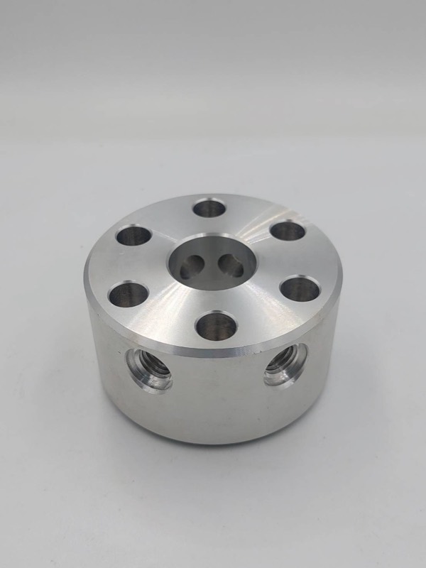
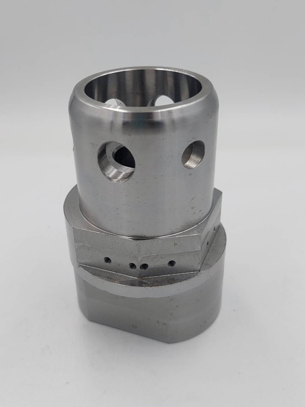
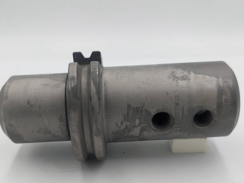
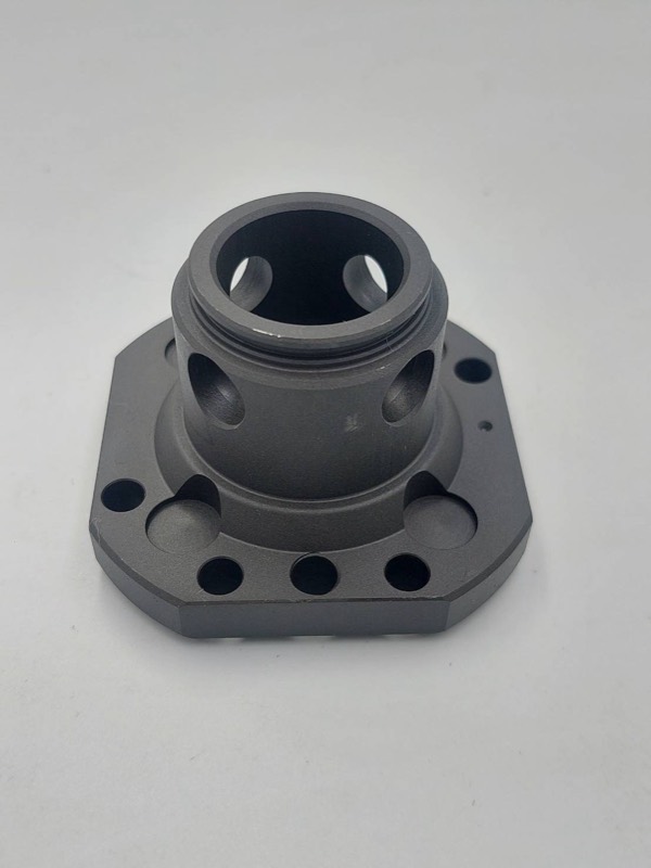
We turn and mill O-ring grooves in aluminum and steel parts such as manifold blocks, valve bodies and flanges to the groove dimensions and finishes on your drawing; if seals must be installed or the part pressure tested, tell us in the RFQ and we confirm it in the quotation.
Frequently asked questions
How much should an O-ring be squeezed?
Typical guidance is up to about 30 % for static seals and about 16 % or less for dynamic seals, with at least about 0.2 mm in all cases. Use your seal maker’s gland table for the exact depth for your cross-section and compound.
Why is gland fill limited to about 85 %?
The ring must have room to swell in the fluid and expand with temperature, and the tolerances of ring and groove stack up. Overfilling forces the ring into the clearance gap, where it extrudes and fails.
Can I use a metric O-ring in an AS568 groove?
Sometimes, if the cross-sections are close, but the squeeze and fill must be recalculated. Design the groove for the ring you will actually buy and name it on the drawing.
What surface finish does an O-ring groove need?
Typically about 32 µin (0.8 µm) on static sealing surfaces, finer for gas and vacuum, and 10–20 µin (0.25–0.5 µm) on dynamic running surfaces, per the Parker handbook. Confirm with your seal supplier.
Should O-ring grooves be anodized?
Anodizing changes groove dimensions and the sealing surface. Many designs mask the groove or size it for the coated state; state which on the drawing and we confirm the approach in the quotation.