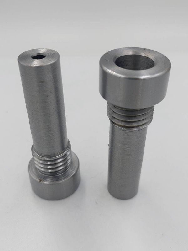
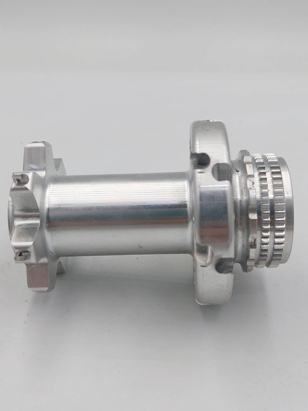
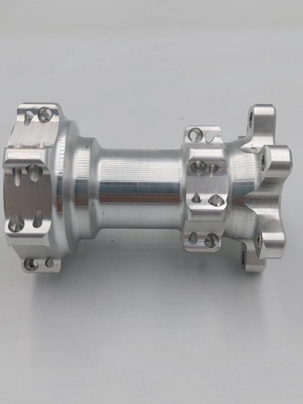
A shaft that turns well has standard features: a DIN 509 relief groove where a ground or fitted diameter meets a shoulder, keyways sized from DIN 6885 (or ANSI B17.1 for inch shafts), circlip grooves to DIN 471, centre holes to DIN 332 where it is turned or ground between centres, and runout callouts tied to a datum axis rather than loose concentricity notes. Keep shoulders few, diameters stepping down from the middle or one end, and slender shafts supported.
Shafts, axles and shaft bolts are among the most common turned parts, and among the easiest to over-complicate. This guide goes feature by feature, with the standard to cite and the information the drawing needs so the shaft can be made and checked without questions.
Shoulders, fillets and relief grooves (DIN 509)
Where a diameter meets a shoulder, a sharp internal corner is a stress raiser, and a bearing or hub cannot seat against it if the corner radius is larger than the part’s own chamfer. There are two clean solutions: a fillet radius smaller than the mating part’s chamfer, or a relief groove (undercut) that lets the mating part sit flat and gives a grinding wheel or tool room to run out.
DIN 509 standardizes these undercuts, so you can call one out instead of drawing it. Form E relieves only the diameter (for grinding the cylindrical surface); Form F relieves both the diameter and the shoulder face (when both are ground); Form G is a smaller combined form with a higher notch effect; Form H uses a larger radius to reduce the notch effect. The designation gives form, radius and depth, for example “DIN 509 – F0.6×0.3”.
- Use an undercut where a diameter is ground or must seat a bearing tight against the shoulder.
- Use a fillet where fatigue matters more than seating; check the mating part’s chamfer clears it.
Keyways: DIN 6885 / ISO 773 and ANSI B17.1
Parallel keys in metric shafts follow DIN 6885-1 (with ISO 773 as the international equivalent): the shaft diameter range selects the key section, and the table gives the shaft keyway depth t1 and hub depth t2. Inch shafts use ANSI B17.1, where the key width is also chosen from the shaft diameter.
- Shaft over 17 up to 22 mm: key 6 × 6, t1 3.5 mm, t2 2.8 mm.
- Shaft over 22 up to 30 mm: key 8 × 7, t1 4.0 mm, t2 3.3 mm.
- Shaft over 30 up to 38 mm: key 10 × 8, t1 5.0 mm, t2 3.3 mm.
- Keyway width fits: normal fit N9 on the shaft with JS9 in the hub; close fit P9 on both; sliding fit H9 on the shaft with D10 in the hub.
- Milled keyways on a shaft are cut with an end mill (rounded ends) or a side cutter (run-out ends). Show which, and dimension the length to the straight part.
- Keep the keyway end away from a shoulder fillet or undercut so the two stress raisers do not stack.
Circlip grooves (DIN 471)
External retaining rings for shafts follow DIN 471 (internal rings for bores follow DIN 472). The ring standard also defines the groove: diameter, width and the minimum distance from the groove to the shaft end. For a 20 mm shaft, the groove is Ø19.0 mm and 1.30 mm wide for a 1.2 mm thick ring.
- Call it out as the groove dimensions with tolerances, or reference the ring standard and size, so it is clear which table applies.
- The groove edge facing the load should be sharp-cornered to carry the ring; break only the outer edge.
- Check the groove does not remove too much section on a highly loaded shaft; a shoulder or a spacer against a nut may be stronger.
- If the shaft is hardened, cut the groove before heat treatment or plan to grind it.
Centre holes (DIN 332) and slender shafts
A long shaft turned between a chuck and a tailstock, or ground between centres, needs a centre hole. DIN 332-1 defines 60° centre holes in types R, A, B and C, and ISO 6411 gives the simplified symbol and designation for drawings, including whether the centre hole may remain on the finished part. Say “centre hole permitted” if you do not mind it — many shops will add one anyway for a long part — or “not permitted” if the end face must be clean.
Slender shafts deflect away from the cutting tool, so the middle comes out larger and less round than the ends. Once the part sticks out more than a few diameters it needs a tailstock centre, and very long thin shafts may need a steady rest or a change of approach. Where you can, step diameters down from one end or the middle, avoid tight tolerances along the full length of a thin section, and give straightness only where it is needed.
Runout and concentricity callouts
For rotating shafts, circular runout or total runout relative to a datum axis is the practical callout. It is checked by rotating the part on its datums and reading an indicator, which matches how the shaft works. Concentricity controls the median points of a feature, is hard to measure and was removed from ASME Y14.5 in the 2018 edition; ISO 1101 keeps concentricity and coaxiality with their own definitions. In most cases runout says what you mean.
- Define the datum axis on the bearing journals (for example a common datum A–B), not on a centre hole or an end face.
- Apply circular runout to diameters that must run true, and to shoulder faces that locate bearings.
- Use total runout where a long surface must be straight and coaxial along its whole length — it is stricter and costlier.
- Diameters turned in the same setup are naturally coaxial; tight runout between features turned in different setups costs more.
Threads on shaft ends
A thread running up to a shoulder needs a runout or an undercut; DIN 76 gives standard thread undercut sizes. Keep the thread diameter below the adjacent journal so the thread does not have to pass over a precision diameter during assembly, and add a chamfer on the thread start. Specify fine pitch explicitly if used, and whether the thread class applies before or after plating — see our thread callout guide for the details.
Checklist for a shaft drawing
These items cover most of the questions a turning shop asks before quoting a shaft.
- Material grade and condition (for example 4140 quenched and tempered), and any hardening with depth and zones.
- Bearing and hub journals with ISO 286 fit codes, roughness and runout to the datum axis.
- Undercuts by DIN 509 designation, keyways by DIN 6885 / ANSI B17.1 size, circlip grooves by DIN 471 size.
- Centre holes: permitted, required (with size) or not permitted.
- Threads with full callout and thread undercuts.
- Finish (black oxide, zinc, anodizing for aluminum) and masking of journals or threads.
Shaft turning at Chi Xin
Chi Xin Technology is a CNC machine shop in Nantun District, Taichung, Taiwan, founded in 2022. We run 5+ CNC machines — 4.5-axis CNC machining centers and CNC lathes — and mainly machine aluminum alloys and alloy steel, with a metal tolerance of 0.02 mm. We also offer wire EDM and surface finishing including anodizing, and we export to customers in Europe and North America.
We turn shafts, axles and shaft bolts in aluminum and alloy steel on our CNC lathes and mill keyways and flats on our 4.5-axis machining centers; if a shaft needs heat treatment or grinding, tell us in the RFQ and we confirm it in the quotation.
Frequently asked questions
What is a DIN 509 undercut?
A standardized relief groove where a diameter meets a shoulder. It lets a mating part seat flat and gives a grinding wheel or tool room to run out. Forms E, F, G and H cover different cases, and the designation gives form, radius and depth.
Should I use concentricity or runout on a shaft?
Runout in most cases. It is measured by rotating the shaft on its datum journals with an indicator, which reflects how the shaft actually runs. Concentricity is harder to measure and rarely adds anything.
How deep is a keyway for a 25 mm shaft?
Per DIN 6885-1, shafts over 22 up to 30 mm use an 8 × 7 key with a 4.0 mm shaft keyway depth and 3.3 mm hub depth.
Do I need centre holes on my shaft?
Not always. Short shafts are turned in the chuck alone. Long or slender shafts, and shafts ground between centres, usually need them. State whether they are permitted on the finished part.
Can you harden shafts after machining?
Tell us the required hardness and zones in the RFQ and we confirm the heat treatment and any grinding in the quotation.